Connecting equipment with Modbus TCP/RTU
Learn the Modbus TCP and RTU settings in the device form, and understand register logic, function codes, and byte order well enough to correctly set up meters, drives, and panels.
«طراحی سیستم» ← «مدیریت ساختار» ← «دستگاهها» ← فرم دستگاه ← زبانهٔ «پروتکلها» (بخش «Modbus TCP/RTU») و زبانهٔ «تنظیمات اتصال» — «طراحی سیستم» ← «مدیریت ساختار» ← «دستگاهها» ← فرم دستگاه ← زبانهٔ «پروتکلها» (بخش «Modbus TCP/RTU») و زبانهٔ «تنظیمات اتصال» — System Design → Structure Management → Devices → device form → the Protocols tab (Modbus TCP/RTU section) and the Connection Settings tab
Modbus is the common language of energy meters, variable-speed drives, chillers, and many industrial controllers. In the digital twin, a Modbus device is defined from the device form just like any other device, and the register map comes from the model's profile in the catalog. This lesson covers the form fields and the concepts needed to read data correctly.
The supported path
The most reliable way is to select the model from the catalog (lesson B2): it builds the model's profile, registers, and data points on save and turns on the protocol. In the catalog's protocols column, models tagged MODBUS_TCP have this capability. Manual register definition from the UI is not supported in the current version; for equipment not in the catalog, the register map is defined on request as part of an integration package.
Get to know the page
The "Modbus TCP/RTU" section on the "Protocols" tab:
| Field | Options | Default |
|---|---|---|
| حمل و نقل (Transport) | Modbus TCP / Modbus RTU / Modbus ASCII | Modbus TCP |
| شناسه واحد (Unit ID) | Number; hint "1-247" | 1 |
| ترتیب بایت (Byte Order) | Big Endian (AB CD) / Little Endian (CD AB) / Mid-Big (BA DC) / Mid-Little (DC BA) | Big Endian |
| فاصله نظرسنجی (Polling Interval) | Seconds; empty means the device default | 60 |
The "Connection Settings" tab for RTU (media "RS-485" or "Modbus (wired)"):
| Field | Options | Default |
|---|---|---|
| پورت سریال (Serial Port) | e.g., COM1 or /dev/ttyS0 | — |
| نرخ باود (Baud Rate) | 2400 to 115200 | 9600 |
| بیت های داده (Data Bits) | 7 / 8 | 8 |
| بیت های توقف (Stop Bits) | 1 / 1.5 / 2 | 1 |
| برابری (Parity) | None / even / odd | None |
Step by step
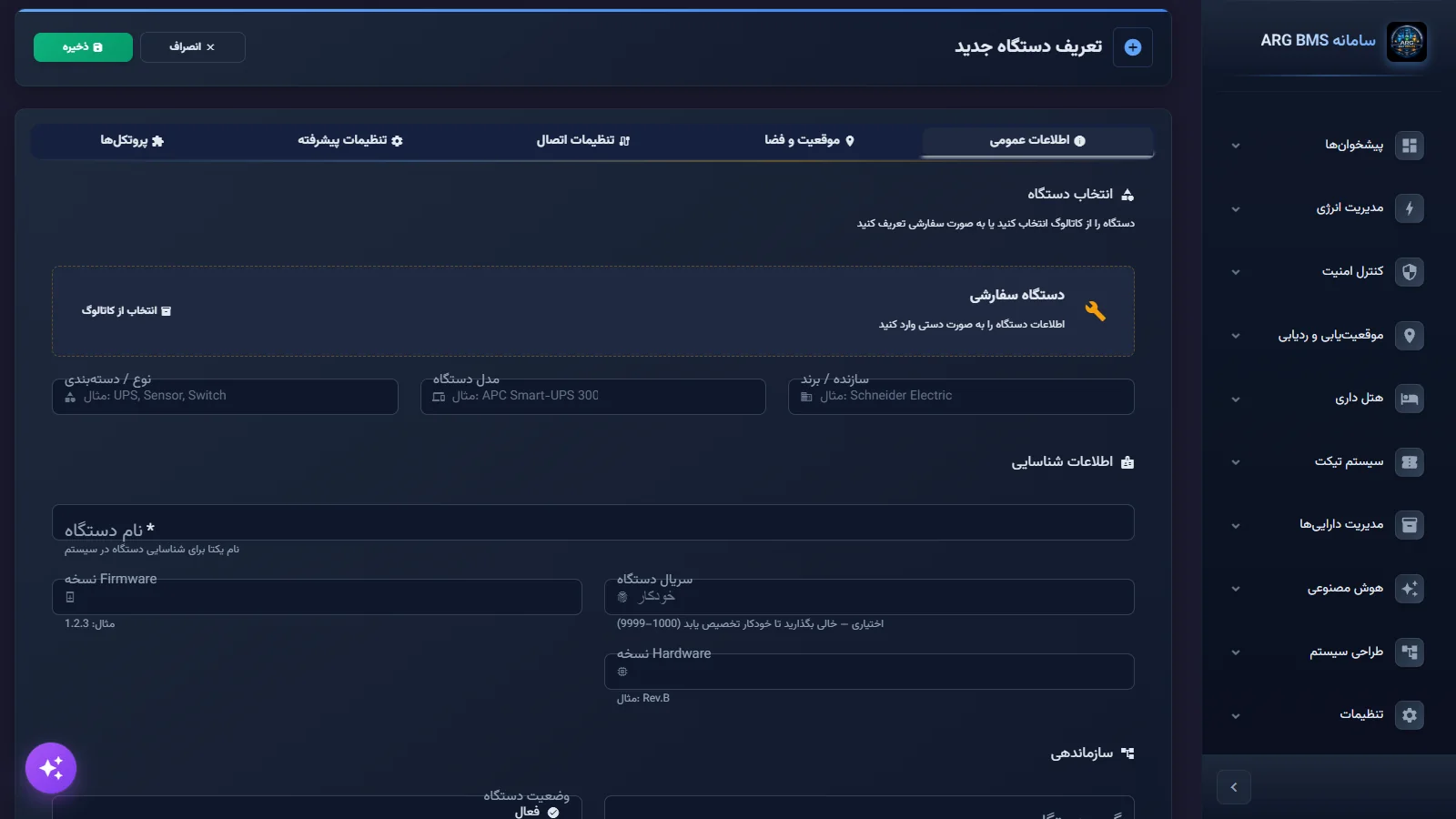
- Select the model from the catalog. In "Define New Device", use باز کردن کاتالوگ (Open Catalog) to select the meter or drive model, and complete the name, space, and group as in lesson B2.
- Set the media and address. On the تنظیمات اتصال (Connection Settings) tab, for Modbus TCP keep the "Ethernet (RJ45)" media, enter the آدرس IP (IP (IP Address)), and set پورت (Port) to 502. For RTU, set the media to "RS-485" and enter the serial port, baud rate, data bits, stop bits, and parity to exactly match the equipment's setting; every device on one RS-485 bus must have the same serial settings.
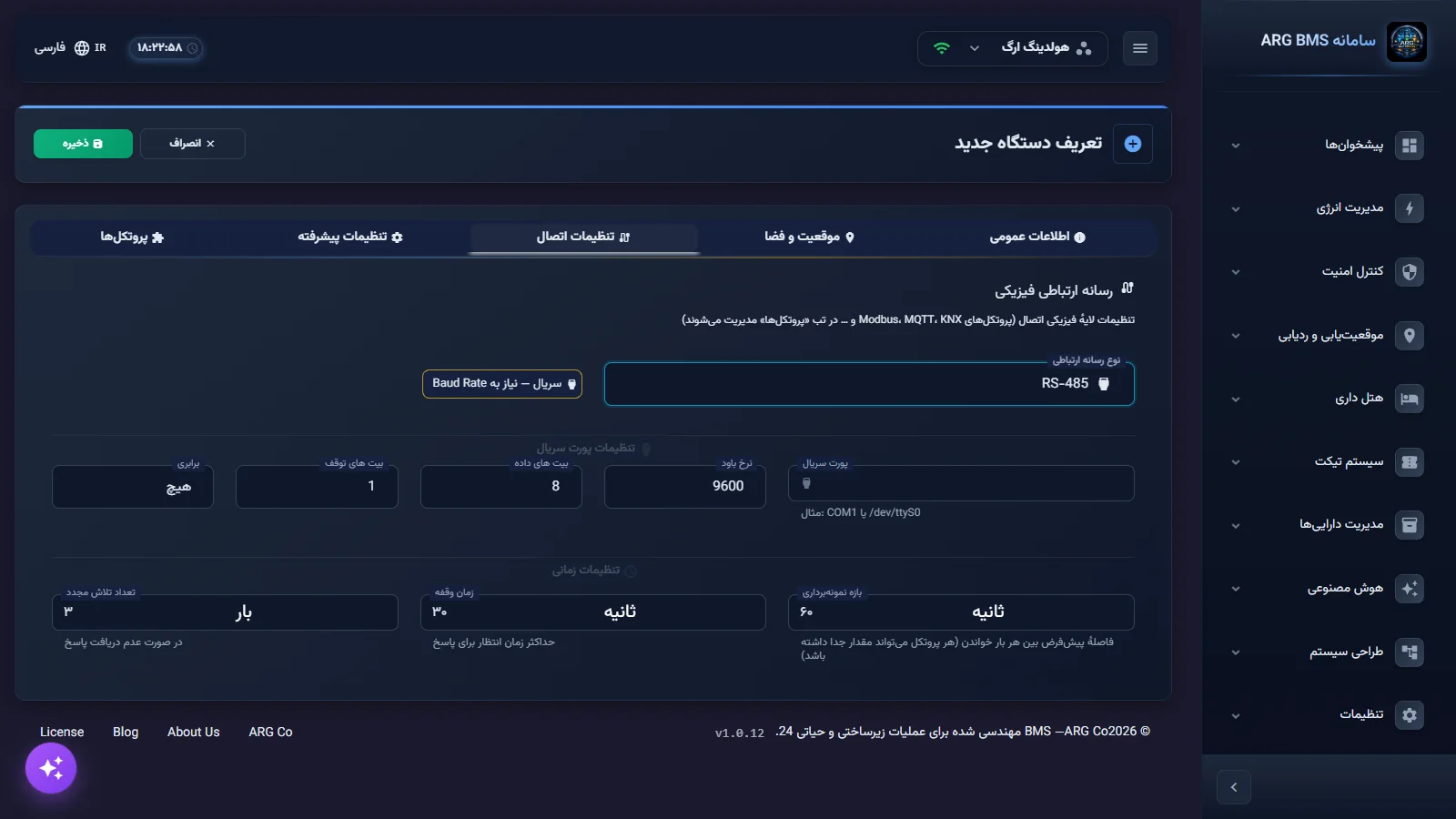
RTU serial settings · Serial port, baud rate, data/stop bits, and parity - Configure the Modbus section. On the پروتکلها (Protocols) tab, turn on the Modbus TCP/RTU section. Set حمل و نقل to match the media, شناسه واحد to match the equipment's slave address, and ترتیب بایت according to the manufacturer's manual. Then click ذخیره (Save).
Modbus section · Transport, unit ID, and byte order - Test the reading. After saving, select the device in the protocol tester (lesson B7) and compare the value of a known register, such as a phase voltage, against the equipment's own display.
What you need before going on site
Most Modbus setup problems come from missing exact equipment information, not from the software. Before you start, complete this list from the manufacturer's manual or the electrical/instrumentation team: transport type (TCP or RTU), network address or serial port, the complete serial setting (baud rate, data bits, stop bits, parity), each device's unit ID on the bus, a register table with register type and data type, the factor and unit for each value, and the byte order of 32-bit values. If the equipment is in the catalog, most of this comes from the model's profile and you only enter the address and unit ID.
Register logic
Every Modbus value is kept in one of four tables. The register type determines which function code reads or writes it:
| Register type | Label | Read | Write |
|---|---|---|---|
| Coil | Coil | FC01 | FC05 or FC15 |
| Discrete Input | DI | FC02 | Read-only |
| Holding Register | HR | FC03 | FC06 or FC16 |
| Input Register | IR | FC04 | Read-only |
Supported data types: Bool, Int16, Int32, UInt16, UInt32, Float32, Float64, and String. 32- and 64-bit values span two or four consecutive registers, and the byte order determines how these registers are read together.
9005. Ready-made server profiles exist for common equipment, including Schneider PM2200/PM5300, Eastron SDM630, ABB ACS580, Danfoss FC302, Carrier 30XA, and APC Smart-UPS.Tips and common mistakes
- "Unit ID" must be between 1 and 247. The form does not reject a value outside this range, so be careful yourself.
- Only two byte orders, Big Endian and Little Endian, are applied in the current version. If the equipment's manual calls for a mid order, coordinate with the implementation team before go-live.
- Manufacturer manuals sometimes number register addresses starting from 1 and sometimes from 0 (e.g., 40001 versus 0). Always check a known value with the protocol tester to avoid an off-by-one-register shift.
- A Float32 value that shows a meaningless or very large number is usually a sign of the wrong byte order.
- A duplicate unit ID on one RS-485 bus causes response collisions.
Summary
- Modbus TCP: Ethernet media, port 502; RTU: RS-485 media with serial settings matching the equipment.
- Registers are built from the catalog profile; register definition for equipment outside the catalog is done on request.
- Holding is read with FC03 and Input with FC04; Input and Discrete Input are read-only.
- The ENID base of Modbus points is 9005.
Hands-on exercise on the live demo
On the public demo, do not save anything.
- At «تنظیمات» ← «کاتالوگ تجهیزات» ← «مدلها» («» ← « » ← «» (Settings → Equipment Catalog → Models)), find an energy meter or UPS tagged MODBUS_TCP in the protocols column.
- In دستگاهها (Devices), open the افزودن دستگاه جدید (Add New Device) form, click دستگاه سفارشی (Custom Device), and go to the پروتکلها tab. Turn on the Modbus section and note the defaults of three fields.
- On the تنظیمات اتصال tab, set the media to RS-485 and write down the default baud rate and parity.
- For a voltage register (Input Register) and a setpoint (Holding Register), write down the read function code; then click انصراف (Cancel).
Lesson check
Answer at least 3 of 4 correctly to pass.
- 1. What is the default Modbus TCP port?
- 2. Which function code reads a Holding Register?
- 3. Which register type cannot be written?
- 4. What is the allowed range for "Unit ID"?